jimbo-0
A simple 8-bit minicomputer
link to repo
I initially started on jimbo as a way to figure out how my computer found the square root of 2. Yes, it sounds weird, but somehow from approximations of the square root turned into computer engineering. It's interesting how interests can change.
I watched a TON of Ben Eater videos (you can see how clear the inspiration is) when trying to learn about how computers worked. And read alot of Wikipedia as well and random stackoverflow forums.
Machine Description
- 8-bit data width
- 11-bit address bus (2KiB available memory)
- 16 instruction architecture
- Output display that supports integers and floating point values
- Bootloader that loads machine code from a micro-SD card
Instruction Set
0000: 0x00: MOV    (R1) (R2 or imm8)    : R1 = R2 or imm8
0001: 0x01: LDR    (R1) (MR or imm16)   : R1 = *MR or *imm16
0010: 0x02: STR    (R1) (MR or imm16)   : *MR or *imm16 = R1
0011: 0x03: ADD  F (R1) (R2 or imm8)    : R1 += R2 or imm8
0100: 0x04: ADC  F (R1) (R2 or imm8)    : R1 += (R2 or imm8) + Carry
0101: 0x05: SUB  F (R1) (R2 or imm8)    : R1 -= R2 or imm8
0110: 0x06: SBB  F (R1) (R2 or imm8)    : R1 -= (R2 or imm8) - Borrow
0111: 0x07: NAND F (R1) (R2 or imm8)    : !(R1 & (R2 or imm8))
1000: 0x08: JMP         (MR or imm16)   : PC = *MR or imm16
1001: 0x09: JNZ         (MR or imm16)   : if (ZERO == 1): PC = *MR or imm16
1010: 0x0A: JNC       (MR or imm16)     : if (CARRY == 1): PC = *MR or imm16
1011: 0x0B: OUT    (R1) (__ or imm8)    : OUT << 8; OUT += R1 or imm8
1100: 0x0C: COT             : OUT = 0x00
1101: 0x0D: HLT                         : HALT CLOCK
1110: 0x0E: MIL    (R1) (__ or imm8)    : MR (LOWER 8 BITS) = R1 or imm8
1111: 0x0F: MIH    (R1) (__ or imm8)    : MR (HIGHER 2 BITS) = R1 or imm8

* F: Flags register updated
* imm16 is in the big-endian format
Instruction Breakdown
XXXX-YYYY
* X: Instruction Word
* Y: Register/Mode
    Addr| R1R2  |    R1    |   M->R1    |   R1->M    |    M     |
    0x0:  A->A,          A,        M->A,        A->M,         M
    0x1:  A->B,          B,        M->B,        B->M,         imm16
    0x2:  A->C,          C,        M->C,        C->M
    0x3:  B->A,          imm8,     imm16->A,    A->imm16
    0x4:  B->B,                    imm16->B,    B->imm16
    0x5:  B->C                     imm16->C,    C->imm16
    0x6:  C->A
    0x7:  C->B
    0x8:  C->C
    0x9:  imm8->A,
    0xA:  imm8->B,
    0xB:  imm8->C,
    ...
    0xF:  imm8->C,      imm8,     imm16->C,    C->imm16,     imm16

* big-endian format followed
Registers
* A Register
* B Register
* C Register - Can also represent an io device
* Flags Register (LSB TO MSB)
    ZERO
    CARRY

* Memory Register
Help from MCUs
Yes, it's kind of weird. A computer inside a computer. But it's not really cheating. The Atemga328p microcontrollers (aka. Arduino Unos) were just there to fill in for really complex or expensive circuitry (for example more ROMs for the 7-segment displays). The bootloader was a really cool thing, and it made it easy to run multiple programs (instead of reflashing a ROM every time)
The build process
I initially threw schematics together in early August of 2023, then ordered parts and built it! Sometimes my friend Jimmy helped me assemble things while we hung out.
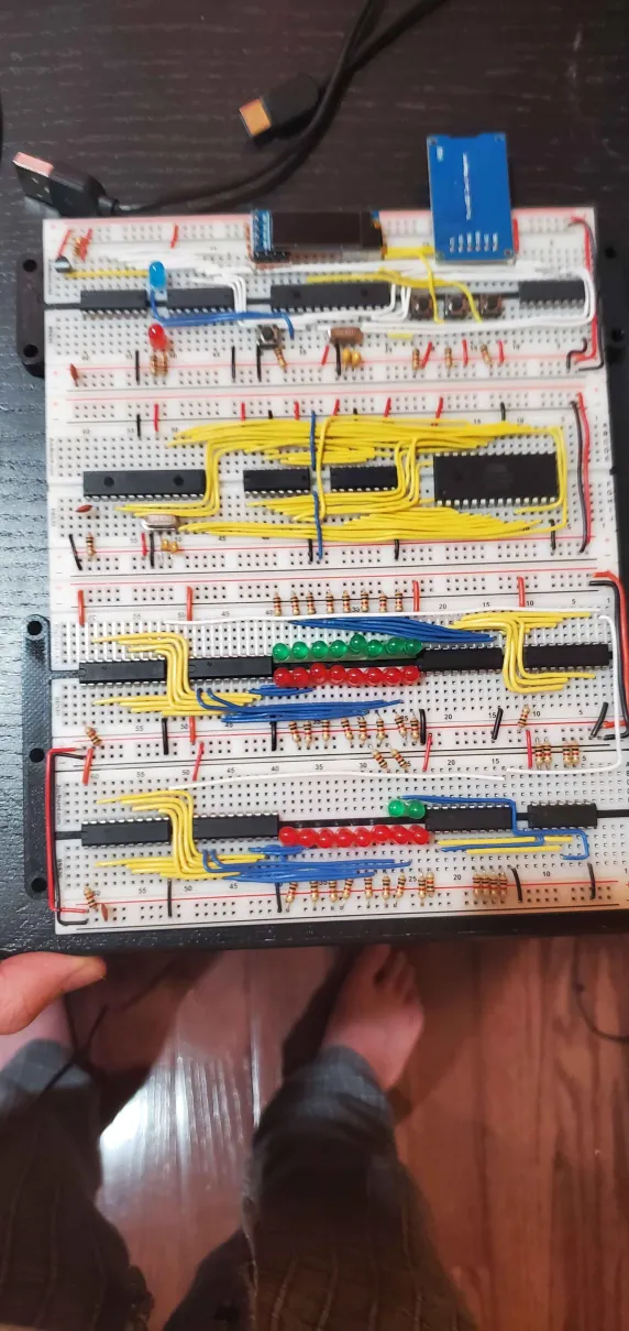
The computer itself:

Video of it running fibonacci
Schematics
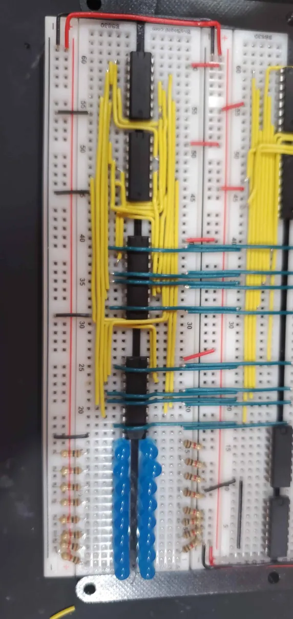
Images of progress while building:
A, B, C Registers and clock/bootloader complete!

ALU Complete (Jimmy's wiring, it's really nice)

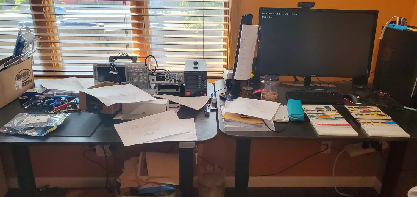
The workstation...
